Core Advantages

Scope

Initially for designing P&ID (Process flow drawings) designing collecting data of selected process pipe lines with our experienced engineers and designed the model with the collected data and listed the total equipments.

Read More

Software & Tools

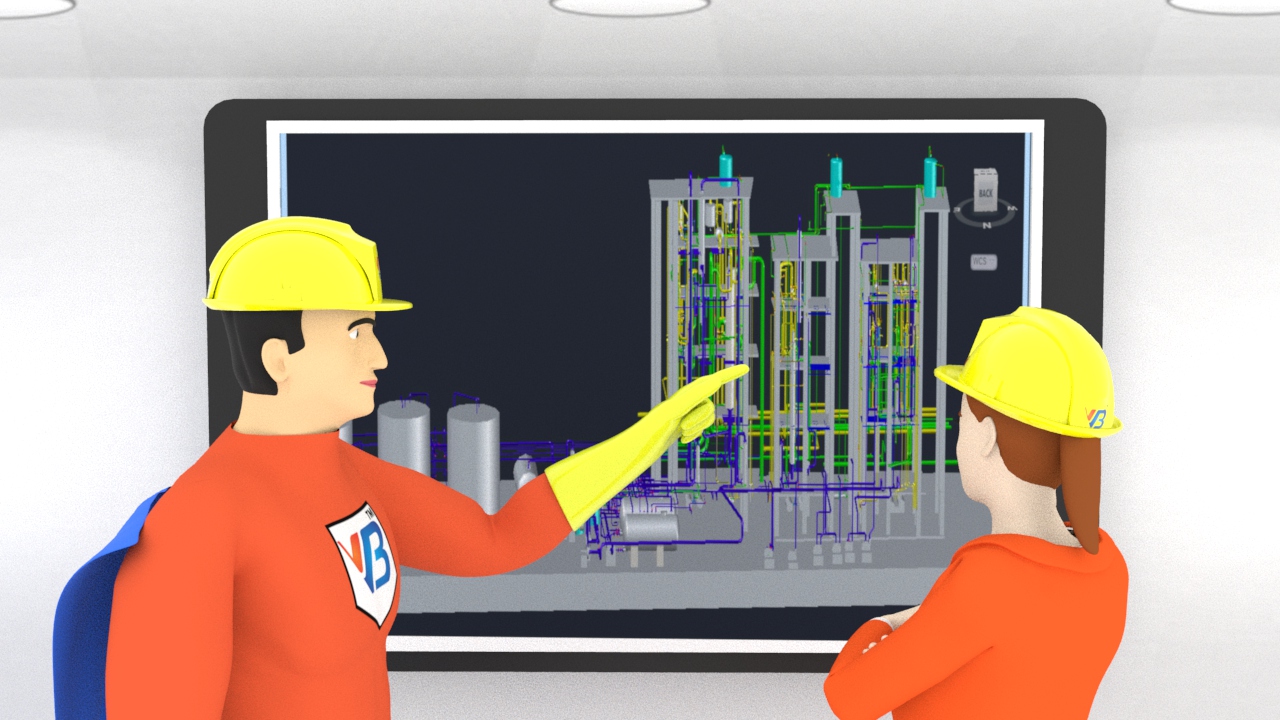
We adopt digital range finders, vernier and tapes for measurements and AUTOCAD Plant 3D software is used for designing P&ID.

Read More

Standards and compliance

We offer this P&ID service in compliance with Autocad Plant 3D PIP, ISA, ISO/DIN and JIS standards.

Read More
piping and instrumentation diagram

Other Offerings

2D Manufacturing Drawings

2D drawing is a drawing that represents in only in X and Y-axis. More simply, a 2D drawing is flat and has a width but ..

Read More

P&ID Drafting & Designing

Piping and instrumentation drawing or P&ID Drawing is used to describe the total engineering process like from the source (Machine/Equipment) to ...

Read More

Fire Escape Floor Plans

Fire Escape Floor plan is one of the foremost providers of CAD services forget the people provide security and safety during working ...

Read More

Reverse-Engineering

Reverse engineering is the process of discovering the technological principles of a device, object or system through analysis of its structure ...

Read More

Lean Simulation

A simulation methodology followed by the world class manufacturing units. Lean manufacturing has been a best practice across the globe ...

Read More

3D Plant Simulation

Either Green field or brown field project, the best practice of the industry is to simulate the system well before investing in it. Visualising a plant or ....

Read More

Process We Follow

Site visit and Data collection

Before going to design the 3D piping model in software some information is required form site and it depends on the project. Need detail information if the project is design from green field/ Brown field. The main details we Assume/Require are

  • Basic sequence process
  • Various Equipments in the sequence process
  • Inlet and outlet connections of Equipments
  • Manual and automatic type of devices and valves using in between pipe connections
  • Material properties and other specifications.

For building the design model the major sequence of order needs to follow.

process and instrumentation diagram

1. Creating Projects For creating model of P&ID this is the initial step of creating Project and follows the next step as well.

2. Creating template For crating this template first, we should fix whether the model is 3D/2D and type of piping.

3. Creating structures From ground level to the top the structure for supporting all the Equipments and devices. So, build the 3Dmodel of Structure if the model is on 3D Isometric.

4. Creating equipments Individually create all the equipments using in the process sequence those are Tanks, vessels, Stand pipes, Heat Exchangers.

5. Adding Specifications and Catlogs For the designed 3Dmodel we need various Specific details need to assign those are Make, Material, size and other flow parameters

6. Routing pipes The running of the pipe is the major task for 3D isometric of P&ID. Without any clashing of Structure and other equipments the pipe lines need to run to reach destination.

7. Adding Valves, Fittings and Pipe Supports For the total flow line, the other devices to the pipe have been included for the regulating the flow of fluid/ other mediums in the pipe.

After completion of designing the total 3D model the exporting of model needs to do for sending to the approval.

1. Creating Isometric Drawings 3D created model is exported to 3D isometric drawings for better visual of structure and pipe routing.

2. Creating Orthographic drawings Detailing of pipe line diagram with all space available for the total building is included length and size of pipe in 2D orthographic drawings.

3. Creating reports Total reports for the model is generated with BOQ for the designed model.

More Features

piping instrumentation

piping and instrumentation diagrams are the fundamentals for any design requirement. P & id plays a vital role when you want to evaluate the existing plant and move for expansion. P&ID drawings need to be created with a specific skill set and experience. P&ID meaning sometimes interpreted as piping and instrumentation and sometimes process and instrumentation drawing. Process and instrumentation diagram serves a different purpose when compared to piping instrumentation drawings.. We need to develop Piping and Instrumentation Diagram (P&ID) of processing plant at design stage, detailing the details of piping and instrumentation and the process flow. The operation of the plant and construction of the plant can be stuide for coordination with reference to the P&ID built. A well experience process design engineers should be employed for developing the P&ID so that instrumentation and piping engineers can make best use of it. The plant should develop a detailed process flow diagram (PFD) capturing the process flow of the and design of the plant from basics. The P&ID developer should consider this process flow diagram (PFD) for design and development of P&ID diagrams. While developing the P&ID drawings the following this should be kept in objective by the designer.

  • Construction integrity evaluation
  • Uniformity in the design and development
  • Symbology and standardization
  • Multiple view capturing for analytical visualization
  • Piping stream and process flow fundamentals

Digital Transformation is in Agenda?

The use should have the clear purpose of making P&ID diagrams weather it is for process and instrumentation drawings purpose or piping and instrumentation drawings purpose. Also is the P&ID preparation is a part of the digital transformation program so tha this can be embedded later into the Digital Twin model of the syste. As p and id is very important for the system analysis especially for brown field projects or projects which are looking for expansion P&ID diagram shall be created very carefully with the accurate dimensions so that both the existing plant and expansion planned will be in sync.

Choose your correct Digital Twin Partner

VB Engineering has an expert team of professionals in providing P& ID drwaings. Either you want piping and instrumentation diagram or Process and instrumentation drawings we have well equipped team with experience to serve your needs of P&ID. VB Engineering is your single point of solution for all your P&ID drawing requirements.Our Solutions in P&ID include onsite data collection with measurements and digitsing the system with library and preparing a full length P&ID digital twin model for the plants.