
DC arc flash · NFPA 70E Annex D · IEEE 1584 limit · battery and UPS
How VB calculates DC arc flash incident energy for UPS, battery and DC distribution.
UPS strings, battery cabinets and DC distribution sit outside the standard everyone cites. VB Engineering models them in ETAP and SKM PowerTools by the NFPA 70E Annex D methods, in the same campus model as the AC switchgear, and labels every DC bus on the signed result. Count your DC equipment on the right, then send the one-line and VB models the first string free.
1,000+ assessments21 countriesSince 2014AC and DC in one table
DC scope estimator
| What VB models | Estimate |
|---|---|
| DC buses in the incident energy table | 22 |
| Data VB collects on the walkdown | 8 battery data sheets · 4 UPS DC-link ratings · 14 DC protective devices |
| Walkdown and modeling effort | about 3 crew days on site, 2 weeks in ETAP or SKM |
| Labels produced | 22 dated DC labels |
Modeled, illustrative scope (category 3): one DC bus per UPS DC link, per battery string or cabinet, per DC board and per 800 VDC hall section; effort from VB's method durations. Estimate opens the short form so a VB engineer can turn the estimate into a per-bus scope from your one-line; the first string is modeled free.
Model the whole string, free
Send the DC one-line or the battery data sheet. A VB engineer models every DC bus in ETAP or SKM with the real DC protection and returns the incident energy table and a label schedule in two business days. Short form, no phone number.
Trusted on plants that cannot stop











- 0where IEEE 1584's validated AC range starts; it ends at 15 kV and never covers DC
- 0modeling platforms VB runs DC studies in: ETAP and SKM PowerTools
- 0campus model for AC and DC buses together, never a spreadsheet
- 0assets twinned and labeled, AC and DC
- 0arc flash assessments delivered
Standard figure: IEEE 1584-2018 clause 1 scope. Platform, asset and assessment counts: VB Engineering project register.
How the free DC model works
- 1
Send the one-line and the battery data
The DC one-line, the string or cabinet short-circuit rating from the data sheet, and the DC protection in the circuit. A photograph of the nameplates is enough.
- 2
VB models every DC bus in ETAP or SKM
UPS DC link, battery string, battery cabinet, DC distribution, 48 V and 800 VDC where present, added to the same campus model as the AC gear. The software derives the arcing time from the DC protection you actually have.
- 3
Table and label schedule in two days
Incident energy, boundary and PPE per bus with the method on the row, plus the dated label artwork. Signed. The first string is free; the rest is scoped per bus.
The gap
Does IEEE 1584 cover DC arc flash?
No. IEEE 1584-2018 is validated for three-phase AC systems from 208 V to 15 kV with bolted fault currents from 500 A to 106 kA, and it gives no DC method. For UPS battery strings, battery cabinets and DC distribution, VB Engineering models incident energy in ETAP or SKM PowerTools by the DC methods in NFPA 70E Informative Annex D, in the same campus model as the AC switchgear, and names the method on every DC row of the incident energy table.
| Standard | What it provides for DC | What it does not | How VB uses it |
|---|---|---|---|
| NFPA 70E 2027 · 130.5 | The duty: an arc flash risk assessment for every piece of electrical equipment, AC or DC, likely to be worked on while energized | A calculation method in the mandatory text | The requirement every DC bus in the campus study is answered to |
| NFPA 70E 2027 · Informative Annex D | The DC incident energy methods: maximum-power (D.5) and the detailed arc-resistance method it references, with enclosure and arcing-time guidance | A mandatory method; the annex is informative and the engineer selects | The methods VB selects in ETAP or SKM for the DC buses; the one used is printed on the label schedule |
| Doan, IEEE Trans. Industry Applications, 2010 | The derivation of the maximum-power method the software implements | Treatment of long arcs or enclosure geometry | Cited in the report so the client's engineer can trace the software's method to its source |
| IEEE 1584-2018 | Nothing for DC | Any DC method; scope is three-phase AC 208 V to 15 kV | The AC side of the same table, so the campus has one method per bus type, both named |
| NFPA 70E 2027 · 130.5(H) and Table 130.7(C)(15)(b) | Label content and the DC PPE category table | Incident energy itself | Label artwork and PPE selection for every DC bus |
| IEEE 1584.1-2022 | The deliverable: what the study report must contain | Any calculation | The 11-section report structure, DC rows included |
| NFPA 855 · IEEE 946 | Battery installation and DC auxiliary system context: spacing, protection, ventilation | Arc flash energy | Read alongside the study so the battery room's protection and clearances are understood before the arcing time is set |
The method
How does VB calculate DC arc flash incident energy?
In ETAP or SKM PowerTools, never by hand or spreadsheet. The DC buses are built into the same campus model as the AC switchgear, every DC protective device is entered with its time-current curve, and the software applies the NFPA 70E Informative Annex D method selected for the study, maximum-power by default, to report incident energy, arc flash boundary and PPE for each DC bus, open-air and enclosed. The engineer reviews every row and signs the table; the label carries the figure the equipment case requires.
| Model input | VB's source | The error a weak study makes |
|---|---|---|
| DC bus voltage | Nominal bus voltage; float voltage for a battery string, from the data sheet | Entering the AC input voltage of the UPS |
| Short-circuit contribution | Battery string or cabinet short-circuit rating, rectifier and UPS DC-link contribution, cable impedance from measured lengths | Carrying the AC-side fault current across to the DC bus |
| DC protection | Every DC fuse and breaker entered with its curve, so the software finds the clearing time at the arcing current; where nothing clears, the study says so | Assuming the upstream AC breaker clears a DC arc it cannot see |
| Equipment case | Open rack or enclosed cabinet, set per bus on the walkdown | One case applied to the whole room |
| Working distance | 457 mm (18 in) for LV DC equipment unless the task dictates otherwise, printed on the label | A label with energy and no distance |
| Method | NFPA 70E Annex D maximum-power by default; the detailed arc-resistance method where the client specification names it; the method recorded on the row | No method stated, so nobody can check the figure |
Why not a calculator or a spreadsheet?
- One model, one plant · the DC buses sit in the same ETAP or SKM model as the AC gear, so a change on the AC side re-rates the DC side automatically
- Real clearing times · the software reads the DC device curve at the arcing current; a spreadsheet takes whatever number is typed in
- Every scenario · utility, generator, UPS bypass and battery-only modes are run as cases, not re-typed
- Traceable · the report carries the model file reference, the method and the software version, so an insurer or a PE reviewer can reproduce any row
- Signed · the engineer who built the model signs the table; a US-licensed professional engineer reviews and stamps on request
Online DC arc flash calculators give one number from four inputs with no protection curve, no case and no signature. VB does not publish one, because a label cannot be built on it. The scope estimator above tells you what VB will model; the model tells you the energy.
A worked example
What does a DC arc flash calculation look like on a UPS battery string?
Three rows from an illustrative model of one 480 V DC UPS battery string with a 20 kA short-circuit rating at 457 mm, run by the NFPA 70E Annex D maximum-power method that ETAP and SKM implement. With a DC fuse clearing in 0.5 s the enclosed incident energy is 34.5 cal/cm²; with a DC breaker clearing in 0.1 s it is 6.9 cal/cm²; with nothing clearing the DC arc it is 137.9 cal/cm², above the 40 cal/cm² ceiling of arc-rated PPE. The protection, not the battery, decides whether the bus can be worked on at all.
| Case | Arcing time | IE open air | IE enclosed | Boundary open / enclosed | Minimum PPE arc rating (enclosed) | What VB writes on the label |
|---|---|---|---|---|---|---|
| DC fuse clears at arcing current | 0.5 s | 11.5 cal/cm² | 34.5 cal/cm² | 141 cm / 245 cm | 40 cal/cm² suit | 34.5 cal/cm² at 457 mm, boundary 245 cm, DANGER |
| DC breaker clears | 0.1 s | 2.3 cal/cm² | 6.9 cal/cm² | 63 cm / 110 cm | 8 cal/cm² | 6.9 cal/cm² at 457 mm, boundary 110 cm, WARNING |
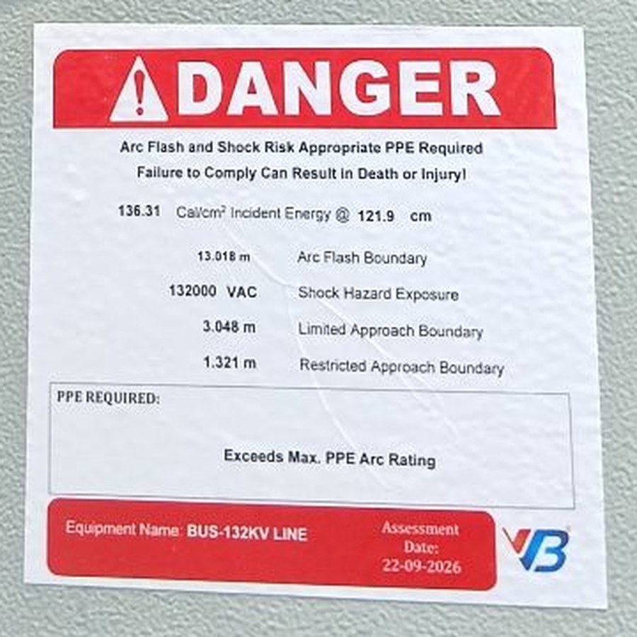
| Nothing clears the DC arc | 2 s (NFPA 70E maximum) | 46.0 cal/cm² | 137.9 cal/cm² | 283 cm / 490 cm | Exceeds arc-rated PPE | Exceeds maximum PPE arc rating; no energized work; engineering control required |
The third row is the one that matters on most campuses VB walks down. The battery string has a fuse, but it is sized for the bolted current and the software shows it never operating at the arcing current, so for the purpose of the label nothing clears the arc. The action register then carries one line that changes the whole room: a DC protective device that clears at the arcing current, re-run in the model before it is bought.
The room
What makes a battery room different from a switchgear room?
Three things. A battery cannot be switched off, so every task on the string is energized work. The DC protection, where it exists, is usually sized for the bolted current and may never see the arcing current, so the arcing time is long. And the energy is often inside a cabinet, so the enclosure multiplier applies. VB's battery room study sets the arcing time from the real protection or says plainly that nothing clears the arc, and labels every cabinet, disconnect and board on that basis.
No off switch
A string is live from the moment the cells are connected. Isolation only separates it from the load; the string itself still carries the full short-circuit energy.
Slow or absent clearing
DC fuses sized for the bolted current may take seconds at half that current, or never operate. The arcing time is where the energy multiplies.
The enclosure effect
Battery cabinets, UPS DC links and DC boards focus the arc energy at the worker. The model is run for the enclosed case on every cabinet and board; VB labels on that figure.
How VB studies UPS strings, battery cabinets and 800 VDC distribution
Every DC bus goes into the same ETAP or SKM model and the same incident energy table as the AC switchgear, with the method named on the row, the arcing time taken from the device curve, and open-air and enclosed cases run per bus. Battery data sheets, rectifier ratings and the DC protection schedule are collected on the walkdown. For 800 VDC distribution in AI halls, where the bus runs at a voltage the Annex D methods were never tested at, VB runs the method, states its limit on the row, and reads it against the independent engineer's view of 800 VDC arc flash. The buy step, a full DC study with labels, is the DC arc flash study service.
Why the DC table carries weight
Written by the team that has labeled 12,547 assets
AC buses by IEEE 1584-2018, DC buses by NFPA 70E Annex D, in one ETAP or SKM model and one incident energy table with the method on every row. No bus is left out because the standard ran out.
Every DC fuse and breaker is in the model with its curve. The software finds the clearing time at the arcing current, and the report writes "nothing clears" where that is the truth.
The engineer who ran the calculation signs the table. A US-licensed professional engineer reviews and stamps the study on request.
The client's engineer sees which case the equipment is in and why the label carries the figure it does.
Data centers, pharma, power and process plants in 21 countries, with UPS and battery rooms in most of them.
Send the one-line; the first DC bus set is modeled at no charge so the client's engineer can check the arithmetic before scoping the rest.
Before you ask
Questions engineers ask VB about DC arc flash
Does IEEE 1584 cover DC arc flash?
No. IEEE 1584-2018 is validated for three-phase AC systems from 208 V to 15 kV, with bolted fault currents from 500 A to 106 kA, and it gives no method for DC. For UPS battery strings, battery cabinets and DC distribution, VB Engineering calculates incident energy by the maximum-power method published by Doan in 2010 and carried in NFPA 70E Informative Annex D.5, and names the method on every DC row of the incident energy table.
Which standard applies to DC arc flash?
NFPA 70E applies. Article 130.5 requires an arc flash risk assessment for DC equipment exactly as for AC, 130.5(H) sets the label content, and Informative Annex D.5 gives the DC incident energy method. IEEE 1584.1-2022 sets the deliverable, and for battery installations NFPA 855 and IEEE 946 set the context the study is read against. VB cites each one to clause level in the report's conformance matrix.
How is DC incident energy calculated under NFPA 70E?
By the DC methods in NFPA 70E Informative Annex D, which VB runs in ETAP or SKM PowerTools rather than by hand. The maximum-power method in D.5 takes the arcing current as half the bolted current and derives incident energy from the bus voltage, the arcing current, the arcing time and the working distance, with a higher figure for an arc inside an enclosure. The software applies the method per bus with the real DC protection curves, and VB reports open-air and enclosed cases and labels on the one the equipment requires.
Does VB use a DC arc flash calculator?
No. VB models DC buses in ETAP or SKM PowerTools inside the same campus model as the AC switchgear, because a calculator takes four typed inputs and gives one number with no protection curve, no operating scenarios and no signature, and a label cannot be built on that. The scope estimator on this page tells you how many DC buses VB will model and what data it needs; the model, run by a named engineer, gives the energy.
Why does VB report an open-air result and an enclosed result?
Because the equipment decides which one applies. A battery string on an open rack is an open-air arc; a battery cabinet, a UPS DC link or a DC distribution board is an enclosed arc, and NFPA 70E Annex D treats the enclosed case as the more severe one. VB sets the case per bus on the walkdown and runs both in the model so the client's engineer can see why the label carries the figure it does.
What are the arc flash requirements for a battery room under NFPA 70E?
The same as any electrical room: an arc flash risk assessment under 130.5, labels under 130.5(H) on every battery cabinet, DC disconnect and DC distribution board, and PPE selected from the incident energy or the DC PPE category table. The battery room is harder than it looks because the DC protection, where it exists, often clears slowly, and the arcing time is what multiplies the energy. VB's study sets the arcing time from the actual DC protection or states plainly that none exists.
Do battery cabinets need arc flash labels?
Yes, where they can be worked on while energized, which is nearly always, because a battery cannot be switched off. NEC 110.16 requires the warning label on equipment likely to require examination while energized, and NFPA 70E 130.5(H) sets what the label carries. VB labels every battery cabinet and DC board in the campus study with the incident energy, the boundary and the assessment date.
Is a DC arc flash study required by code?
The label is code and the assessment is a standard, for DC just as for AC. NEC 110.16 requires the arc flash warning on DC switchboards, panelboards and similar equipment; NFPA 70E 130.5 requires the risk assessment that produces the figures; OSHA enforces both through 29 CFR 1910.132(d). A campus study that stops at the UPS input and leaves the DC side unlabeled satisfies none of the three for the battery room.
Does a DC label need a working distance?
Yes. The incident energy on a label is meaningless without the distance it was calculated at, and NFPA 70E 130.5(H) requires either the incident energy and its working distance or the PPE category. VB uses 457 mm (18 in) for LV DC equipment unless the task or the enclosure dictates otherwise, and prints the distance on the label beside the energy.
What happens after I send my DC one-line?
A VB practice engineer builds every DC bus on it, UPS strings, battery cabinets, DC distribution and any 48 V or 800 VDC system, into an ETAP or SKM model with your actual DC protection, and sends back the incident energy table, open-air and enclosed figures, the boundaries and a label schedule within two business days. The first string is modeled free. No call unless you ask for one.
Every DC bus in the same table as the AC gear, method named, first string free.
Send the DC one-line or the battery data sheet. Incident energy, boundaries and a label schedule back in two business days, modeled in ETAP or SKM, signed, yours to forward.
Model my DC systemPrefer email? Send the one-line to connect@groupvb.com with "DC" in the subject line.